Why do I need to become a member?
How do I become a member?
Send me straight to the membership form.
Cables and Transformers

Noise
The number one problem with cables is noise. This is usually due to poor placement of the cables, poor grounding, connections between balanced and unbalanced lines, or equipment with proprietory grounding standards. While most problems can be cured by the use of isolation transformers, it must be remembered that isolation transformers are expensive and by their nature reduce bass and amplify treble. A simple rewiring of a cable end can give a better result.
Transformers
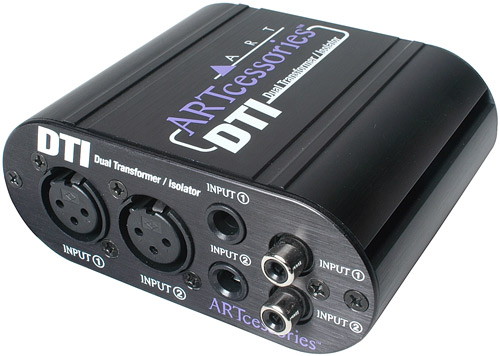
Isolation: An isolation transformer electrically isolates equipment by using an electromagnetic field instead of a direct connection to transfer the 'sound' from one piece of equipment to another. The problem with isolation transformers is that they are limited to physics. A transformer cannot be as efficient at 20 Hz as it is at 20,000 Hz. Even with this problem, most people will not be able to hear the sound degradation.
Impedance matching: Another function of a transformer is impedance matching. Consumer audio electronics and professional audio electronics run at different impedances. If you end up having to run equipment with the volume turned all the way up or down, you will probably get less distortion by using a transformer.
Look at some of the links at the bottom of this page for more information.
XLR
The main connector you will see is the 3 pin XLR connector. This connector and its cable is designed to reduce noise. The cable functions similarly to cat5 cable in that there are 2 twisted wires inside which are supposed to neutralize electromagnetic noise by canceling it out. This canceling effect is caused by the noise waves hitting both the twisted wires at the same time, hopefully only raising or lowering the voltage from them to the outside world, not to each other. This cable is known as a balanced cable, with the audio signals being opposite and equal to each other in theory. It also has a ground shield around the twisted wires to further reduce noise.
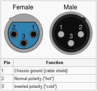
XLR pinout
The table to the right shows the standard XLR pinout. More about it can be found here.
Food for thought
Quote from an old time electrician, "To get shielding, you only hook up one end of the shield. Leave the termination end unhooked. That is the way all of industry does it for instrumentation, and the way we hook up audio. If you hook up both ends, you will get all kinds of noise. Of course if you have to use the shield for a conductor, you have to." Is he right? I think he is. Dig around in the links below and make up your own mind.
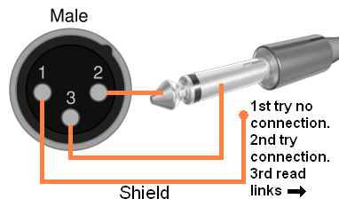
XLR to unbalanced connectors
Consumer and lower end commercial equipment may use unbalanced cables with RCA or TS connectors. These cables are more subject to electromagnetic noise than the balanced type but if you are careful, they work fine. The problem is when you need to convert from XLR to RCA connectors or XLR to TS connectors. Expensive balanced to unbalanced converters or transformers may be bought, but first try a converter cable. You can either buy or make these cables yourself.
Beware: Store bought converter cables may cause a hum. The termination point(s) of the shield is something often done by 'trial and error'. A store bought cable with molded ends can be bad news.
Yamaha M406 Example
From the manual:

XLR to unbalanced schematic:
Links
I know nothing about their equipment, but Rane sure makes good information pages. I would be tempted to try their equipment just for that reason.
Here is an explanation about balanced to unbalanced hookups.
Here is an audio grounding resource.
Here is why you use the shield. (At least on one end.)
- Login to post comments
Posted by MarvinD on Tue, 09/15/2009 - 17:13